Page History
...
- Ports Node When defining ports { }, you must set #address-cells = <1>; and #size-cells = <0>;. For more information, see the documentation in the kernel source: Documentation/devicetree/bindings/media/video-interfaces.txt
- Resolution and Clock Definitions: An LCD Panel will have it's own separate driver. That driver will define the clock rate and resolution. The Renesas LCD driver will then get that information in order to set up the LCD controller (DU) output.
- MIPI DSI Overview: Here is a good article explaining the MIPI DSI interface, packets and commands.: https://circuitcellar.com/resources/quickbits/mipi-display-serial-interface
- MIPI DCS Commands: Many (most) MIPI DSI Panels require setup command (DCS) to be set over MIPI DSI to configure the panel's controller before pixel data can be sent. This is why there is usually a separate driver for each LCD since these commands are specific to each LCD panel.
- Simple-Panel Driver: If your panel requires no special setup (no MIPI DSI DCS commands) or your system is configuring your LCD manually over I2C, or you are using a parallel RGB panel that typically requires no setup, you can use the kernel's "simple-panel" driver. The main reason is that you need to tell the kernel about the resolution and pixel timing is of your panel, but that information is not described in a Device Tree, it must come from a source code driver file. The panel-simple driver is there as a way to do that by simply adding in a new entry for your custom panel. Note that you will be required to edit the driver file (drivers/gpu/drm/panel/panel-simple.c) to add your specific panel resolution and timing that you want. See kernel documentation Documentation/devicetree/bindings/panel/simple-panel.txt.
- Parallel RGB LCD: Since a parallel LCD does not need any special setup, you can use simple-panel driver in the kernel.
- Check Display Settings: You can use the command modetest -M rcar-du -c to check the status of your display driver. It will also show you the supported resolutions of your display (in the case that you are using an HDMI interface where it will read what is supported by the HDMI panel).
- Check VBLANK Timings: You can use the command vbltest -M rcar-du to check the VBLANK timings. If your result is always around 60Hz, your panel is set correctly.
...
| Expand | ||
|---|---|---|
| ||
&du {
status = "okay";
};
&dsi0 {
status = "okay";
#address-cells = <1>;
#size-cells = <0>;
ports {
#address-cells = <1>;
#size-cells = <0>;
port@1 {
dsi0_out: endpoint {
remote-endpoint = <&panel_in>;
data-lanes = <1 2>;
};
};
};
panel@0 {
compatible = "ilitek,ili9881c";
reg = <0>;
dsi-lanes = <2>;
enable-gpios = <&pinctrl RZG2L_GPIO(43, 0) GPIO_ACTIVE_HIGH>;
backlight = <&backlight>;
status = "okay";
port {
panel_in: endpoint {
remote-endpoint = <&dsi0_out>;
};
};
};
};
|
| Expand | ||
|---|---|---|
| ||
&pinctrl {
	du_pins: du {
		data {
			pinmux = <RZG2L_PORT_PINMUX(7,  2, 1)>,
				 <RZG2L_PORT_PINMUX(8,  0, 1)>,
				 <RZG2L_PORT_PINMUX(8,  1, 1)>,
				 <RZG2L_PORT_PINMUX(8,  2, 1)>,
				 <RZG2L_PORT_PINMUX(9,  0, 1)>,
				 <RZG2L_PORT_PINMUX(9,  1, 1)>,
				 <RZG2L_PORT_PINMUX(10, 0, 1)>,
				 <RZG2L_PORT_PINMUX(10, 1, 1)>,
				 <RZG2L_PORT_PINMUX(11, 0, 1)>,
				 <RZG2L_PORT_PINMUX(11, 1, 1)>,
				 <RZG2L_PORT_PINMUX(12, 0, 1)>,
				 <RZG2L_PORT_PINMUX(12, 1, 1)>,
				 <RZG2L_PORT_PINMUX(13, 0, 1)>,
				 <RZG2L_PORT_PINMUX(13, 1, 1)>,
				 <RZG2L_PORT_PINMUX(13, 2, 1)>,
				 <RZG2L_PORT_PINMUX(14, 0, 1)>,
				 <RZG2L_PORT_PINMUX(14, 1, 1)>,
				 <RZG2L_PORT_PINMUX(15, 0, 1)>,
				 <RZG2L_PORT_PINMUX(15, 1, 1)>,
				 <RZG2L_PORT_PINMUX(16, 0, 1)>,
				 <RZG2L_PORT_PINMUX(16, 1, 1)>,
				 <RZG2L_PORT_PINMUX(17, 0, 1)>,
				 <RZG2L_PORT_PINMUX(17, 1, 1)>,
				 <RZG2L_PORT_PINMUX(17, 2, 1)>;
		};

		sync {
			pinmux = <RZG2L_PORT_PINMUX(6, 1, 1)>, /* HSYNC */
				 <RZG2L_PORT_PINMUX(7, 0, 1)>; /* VSYNC */
		};

		de {
			pinmux = <RZG2L_PORT_PINMUX(7, 1, 1)>; /* DE */
		};

		clk {
			pinmux = <RZG2L_PORT_PINMUX(6, 0, 1)>; /* CLK */
		};
	};
};
panel_rgb: panel-rgb {
      	rgb-dummy {
		compatible = "renesasarm,rgbrtsm-dummydisplay"; //<-- this property "arm,rtsm-display" is an example.
                                             // please fill in the correct information based on your panel spec.
      		port {
        		panel_in_rgb: endpoint {
          					remote-endpoint = <&du_out_rgb>;
       			};
     		};
};
&du {
	pinctrl-0 = <&du_pins>;
	pinctrl-names = "default";
	status = "okay";

	ports {
		port@0 {
			du_out_rgb: endpoint {
						remote-endpoint = <&panel_in_rgb>;
			};
		};
	};
};
&dsi0 {
	status = "disabled";
}; |
| Expand | ||
|---|---|---|
| ||
&pinctrl {
	du_pins: du {
		data {
			pinmux = <RZG2L_PORT_PINMUX(7,  2, 1)>,
				 <RZG2L_PORT_PINMUX(8,  0, 1)>,
				 <RZG2L_PORT_PINMUX(8,  1, 1)>,
				 <RZG2L_PORT_PINMUX(8,  2, 1)>,
				 <RZG2L_PORT_PINMUX(9,  0, 1)>,
				 <RZG2L_PORT_PINMUX(9,  1, 1)>,
				 <RZG2L_PORT_PINMUX(10, 0, 1)>,
				 <RZG2L_PORT_PINMUX(10, 1, 1)>,
				 <RZG2L_PORT_PINMUX(11, 0, 1)>,
				 <RZG2L_PORT_PINMUX(11, 1, 1)>,
				 <RZG2L_PORT_PINMUX(12, 0, 1)>,
				 <RZG2L_PORT_PINMUX(12, 1, 1)>,
				 <RZG2L_PORT_PINMUX(13, 0, 1)>,
				 <RZG2L_PORT_PINMUX(13, 1, 1)>,
				 <RZG2L_PORT_PINMUX(13, 2, 1)>,
				 <RZG2L_PORT_PINMUX(14, 0, 1)>,
				 <RZG2L_PORT_PINMUX(14, 1, 1)>,
				 <RZG2L_PORT_PINMUX(15, 0, 1)>,
				 <RZG2L_PORT_PINMUX(15, 1, 1)>,
				 <RZG2L_PORT_PINMUX(16, 0, 1)>,
				 <RZG2L_PORT_PINMUX(16, 1, 1)>,
				 <RZG2L_PORT_PINMUX(17, 0, 1)>,
				 <RZG2L_PORT_PINMUX(17, 1, 1)>,
				 <RZG2L_PORT_PINMUX(17, 2, 1)>;
		};

		sync {
			pinmux = <RZG2L_PORT_PINMUX(6, 1, 1)>, /* HSYNC */
				 <RZG2L_PORT_PINMUX(7, 0, 1)>; /* VSYNC */
		};

		de {
			pinmux = <RZG2L_PORT_PINMUX(7, 1, 1)>; /* DE */
		};

		clk {
			pinmux = <RZG2L_PORT_PINMUX(6, 0, 1)>; /* CLK */
		};
	};
};
	rgb-dummy {
		compatible = "renesas,rgb-dummy";
		ports {
			#address-cells = <1>;
			#size-cells = <0>;

			port@0 {
				reg =
		ports {
			#address-cells = <1>;
			#size-cells = <0>;

			port@0 {
				reg = <0>;
				rgb_in: endpoint {
					remote-endpoint = <&du_out_rgb>;
					};
				};
				port@1 {
					reg = <1>;
						rgb_out: endpoint {
							remote-endpoint = <&panel_in>;
						};
				};
			};
		};
panel {
	/*
	* Define code for panel here such as compatible, backlight, power,...
	* Can refer drivers/gpu/drm/panel/panel-simple.c
	*/
	port {
		panel_in: endpoint {
			remote-endpoint = <&rgb_out>;
		};
	};
};
&dsi0 {
	status = "disabled";
};
&du {
	pinctrl-0 = <&du_pins>;
	pinctrl-names = "default";

	ports {
		port@0 {
			du_out_rgb: endpoint {
				remote-endpoint = <&rgb_in>;
			};
		};
	};
 };
|
...
- The Link Status input pin (LINKSTA) is not used. The driver instead relies on the PHY to inform it that the link is up by using in-band status messages on the RGMII lines.
- Do not forget to set the correct voltage levels for the pins (3.3v, 1.5v, etc..) in the device tree in the pinctrl node.
- You use the syntax "power-source = <3300>;" when you declare the pins for Ethernet.
- Refer to the pinctrl documentation in the kernel for more info.
- Documentation/devicetree/bindings/pinctrl/renesas,rzg2l-pinctrl.yaml
- Documentation/devicetree/bindings/pinctrl/renesas,pcf.yaml
- In the Device Tree, the MDIO address is set by @x@x and the "reg =<x><x>;" For example, MDIO address of 0:
...
If you did not connect the USB_OVCUR pin on your board, and it floats, you will get interrupt messages about over current. However, you can disable this interrupt by modifying the setting for the OHCI HcRhDescriptorA OHCI HcRhDescriptorA Register and setting bit NOCP to bit NOCP to '1'. Search for "HcRhDescriptorA" in the hardware manual for more information.
In the kernelthe kernel, in file driversfile drivers/usb/host/ohci-hcd.c, you want to comment out the to comment out the line:
/* Configure for per-port over-current protection by default */
val &= ~RH_A_NOCP;
In u-boot, can see this is sometimes done for Renesas boards. See file boardfile board/renesas/rzg2l-dev/rzg2l-dev.c
(*(volatile u32 *)(USB1_BASE + HcRhDescriptorA)) |= (0x1u << 12); /* NOCP = 1 */
- Dynamic changing from Device and Host for OTG:
If you are using a device as OTG (On-the-Go) and want to change from device to you, you set a sysfs setting under the PHY driver (not the USB controller driver)
$ echo host > /sys/devices/platform/soc/ee080200.usb-phy/role
Device Tree Examples
- (see device tree for evaluation board)
...
- Given the Device Tree example below for SPI-1, you will need to determine the values for the "tx" and "rx" DMA triggers.
| HTML |
|---|
<pre> &spi1 { pinctrl-0 = <&spi1_pins>; pinctrl-names = "default"; dmas = <&dmac <span><font color=red> 0x2e99 |
...
</font></span>>, <&dmac <span><font color=red> 0x2e9a |
...
</font></span>>; dma-names = "tx", "rx"; status = "okay"; }; </pre> |
- You can find some explanation in the kernel documentation: Documentation/devicetree/bindings/dma/renesas,rz-dmac.yaml
...
- These values are what get written directly to the DMA registers. Also, the values for these bits are fixed and shown in a table in the hardware manual.
- If you look in the Direct Memory Access Control (DMA) chapter in the hardware manual, you will find the table "On-Chip Module Requests"
Example: RZ/G2L RSPI ch1
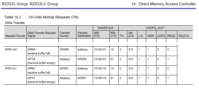

SPIT1 (tranmit buffer empty) dma-names = "tx"
...
  MID[7:0] = 10100110'b
  RID[1:0] = 10'b
  HEIN = 1'b
  LVL = 1'b
  AM[2:0] = 010'b
  TM = 0'b

  AM    HEIN       RID
  |     |          |
0 010 1 1 10100110 10 = 0010 1110 1001 1010 =  0x2e9a
|     |   |
TM    LVL MID
Device Tree Examples
- (see device tree for evaluation board)
I2C
Linux Drivers
...
- device tree for evaluation board)
I2C
Linux Drivers
- RZ/G2H, G2M, G2N, G2E:
- compatible = "renesas,rcar-gen3-i2c"
- drivers/i2c/busses/i2c-rcar.c
- CONFIG_I2C_RCAR=y
- compatible = "renesas,rcar-gen3-iic" (I2C for PMIC)
- drivers/i2c/busses/i2c-sh_mobile.c
- CONFIG_I2C_SH_MOBILE
- compatible = "renesas,rcar-gen3-i2c"
...
- =y
- RZ/G2L, G2LC, G2UL, V2L:
- drivers/i2c/busses/i2c-riic.c
- CONFIG_I2C_RIIC=y
Notes
- The frequency for the driver i2c-rcar.c is hard coded to 100kHz. If you want to change it, you have to modify function rcar_i2c_clock_calculate( )
Device Tree Examples
- (see device tree for evaluation board)
SPI
Linux Drivers
- MSIOF: RZ/G2H, G2M, G2N, G2E:
- CONFIG_xxx=y
- RSPI: RZ/G2L, G2LC, G2UL, V2L:
- drivers/spi/spi-rspi.c
- CONFIG_SPI_RSPI=y
...
- spidev:
- If you want a generic SPI device (/dev/spi-0), in the past you would allocate a compatible = "spidev"; node. Unfortunately, that spidev name has been removed from Linux (since Linux-5.17). However, you can still create a spidev device by simply using another name that is already in the kernel. The compatible name will be different, but it will work the exact same way.
- Below is the list of device that can be used with spidev from file drivers/spi/spidev.c
static const struct of_device_id spidev_dt_ids[] = {
    { .compatible = "rohm,dh2228fv" },
    { .compatible = "lineartechnology,ltc2488" },
    { .compatible = "ge,achc" },
    { .compatible = "semtech,sx1301" },
    { .compatible = "lwn,bk4" },
    { .compatible = "dh,dhcom-board" },
    { .compatible = "menlo,m53cpld" },
    {},
};
For example, if you just pick the first name in the list ("rohm,dh2228fv") this will work on any kernel version:
&spi1 {
	pinctrl-0 = <&spi1_pins>;
	pinctrl-names = "default";
	status = "okay";
	dmas = <&dmac 0x2e99>,
	       <&dmac 0x2e9a>;
	dma-names = "tx", "rx";

    spidev@0{
        compatible = "rohm,dh2228fv"; // (Using fake name to use spidev driver)
        reg = <0>;
        spi-max-frequency = <1000000>;
    };
};
Device Tree Examples
- (see device tree for evaluation board)
...
Overview
Content Tools